I joined the Hackaday workshop on how to solder today :)
It was organized by Matt Berggren. Thank you so much Matt!
We made 3 boards today:
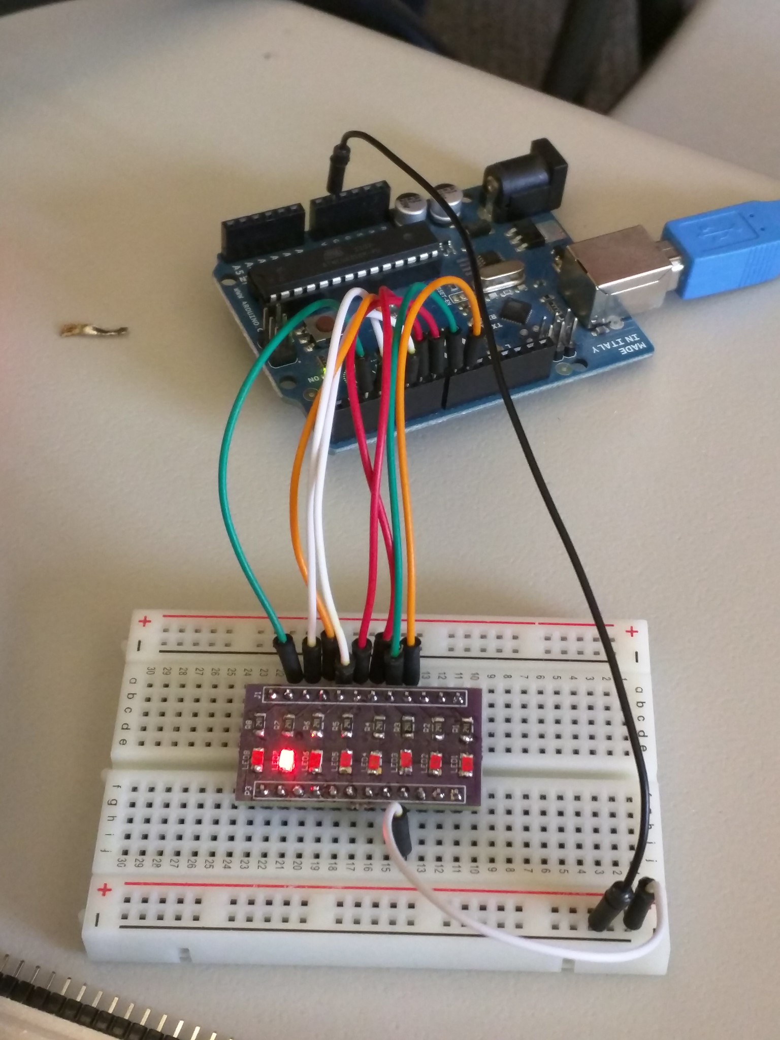
Board #1 – Simple LED Breakout Board

This is the first board of the day... very simple :)
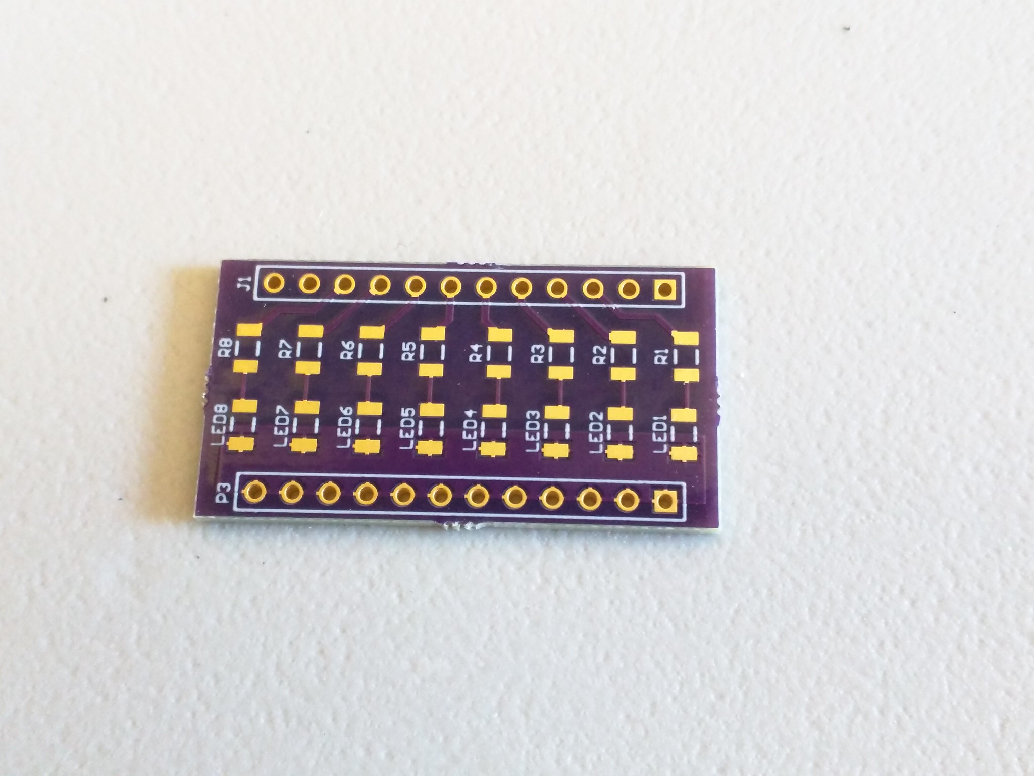
Soldered all of the resistors and LEDs.
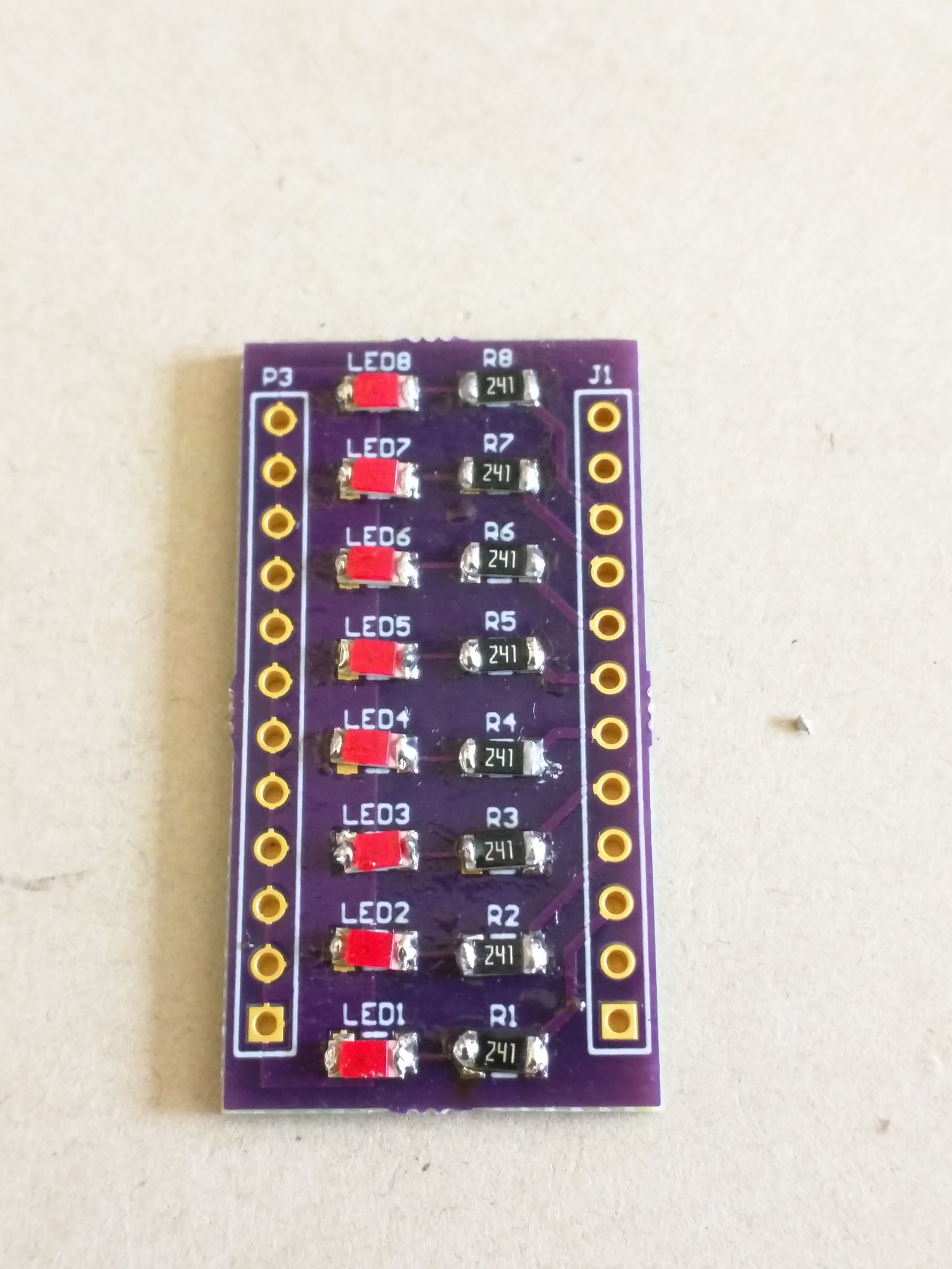
Works!
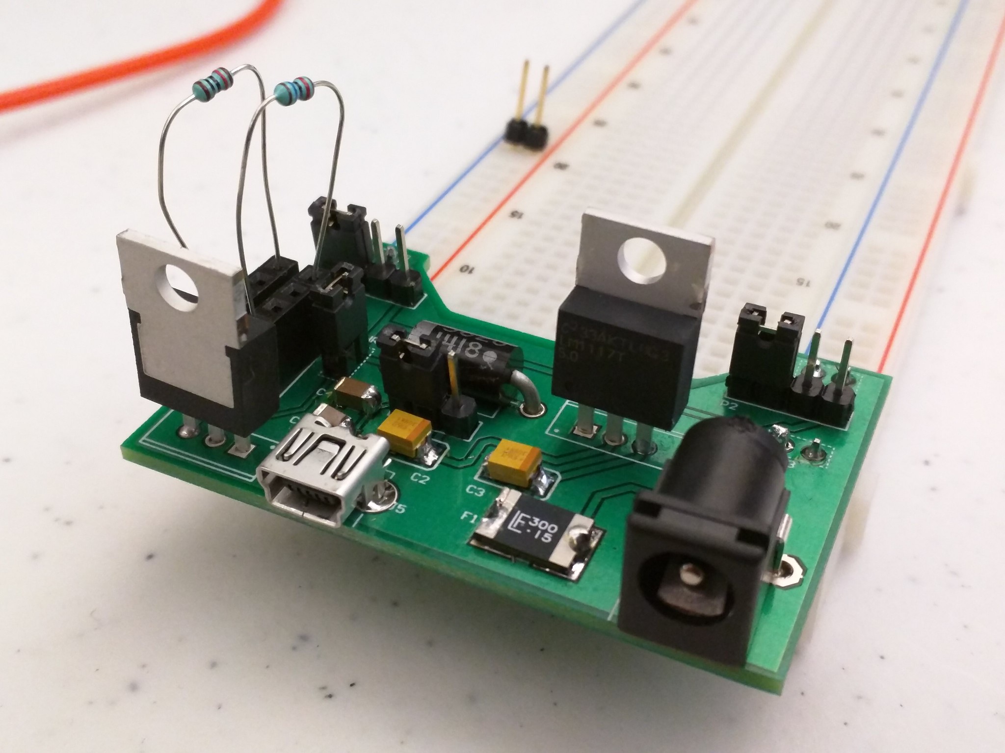
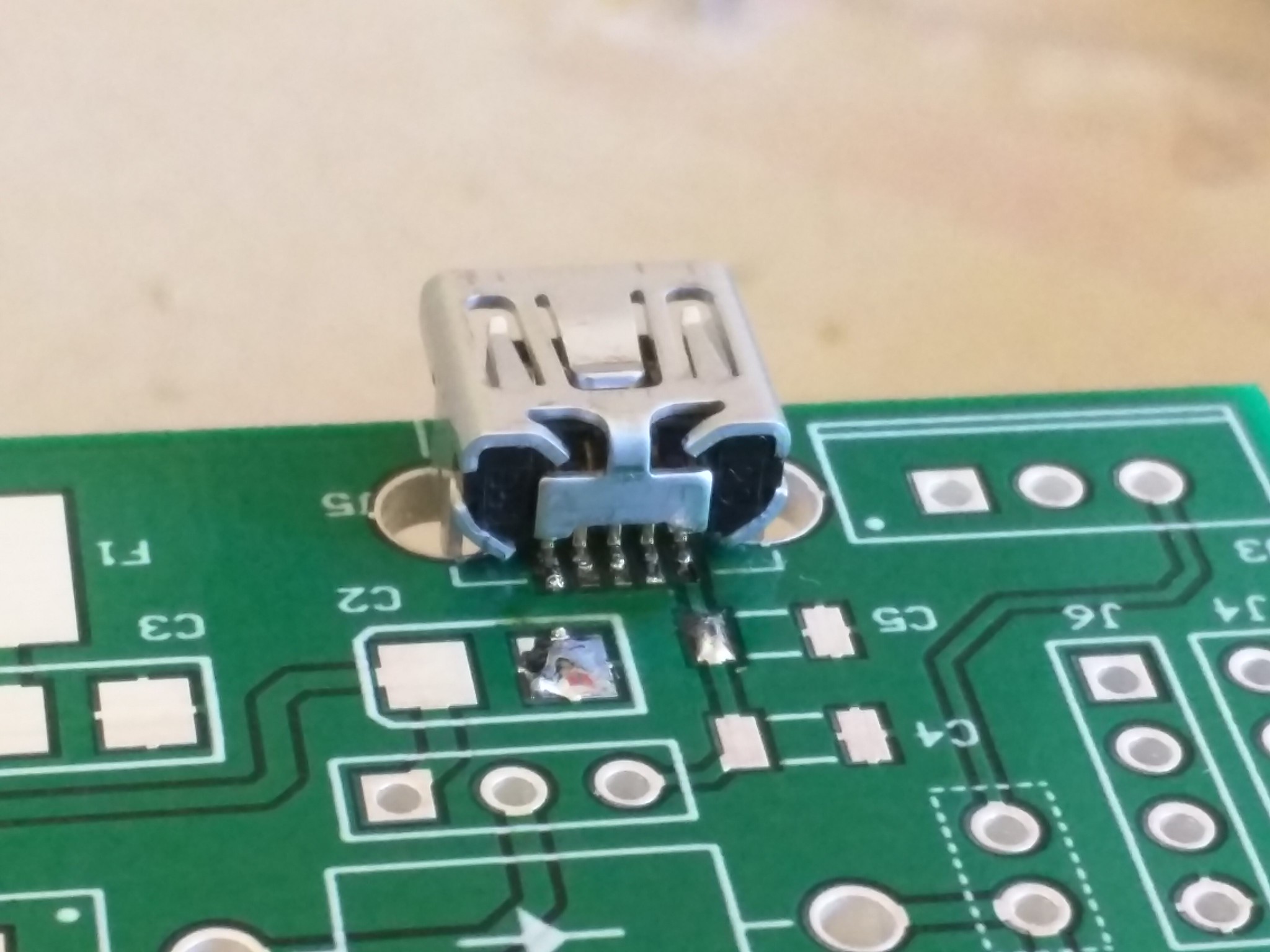
Board #2 – Configurable Breadboard Power Supply


First step: solder the USB port. It's so tiny and hard!
Solder all other parts.
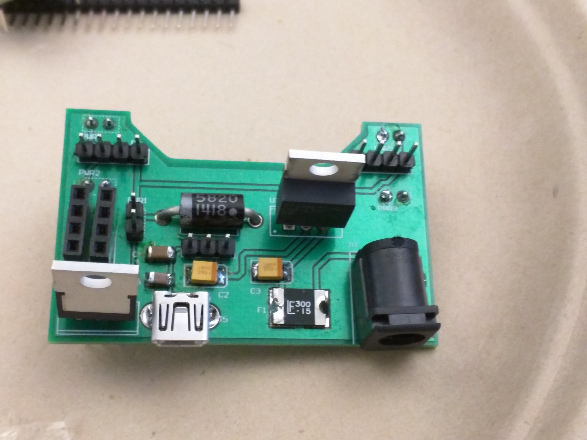
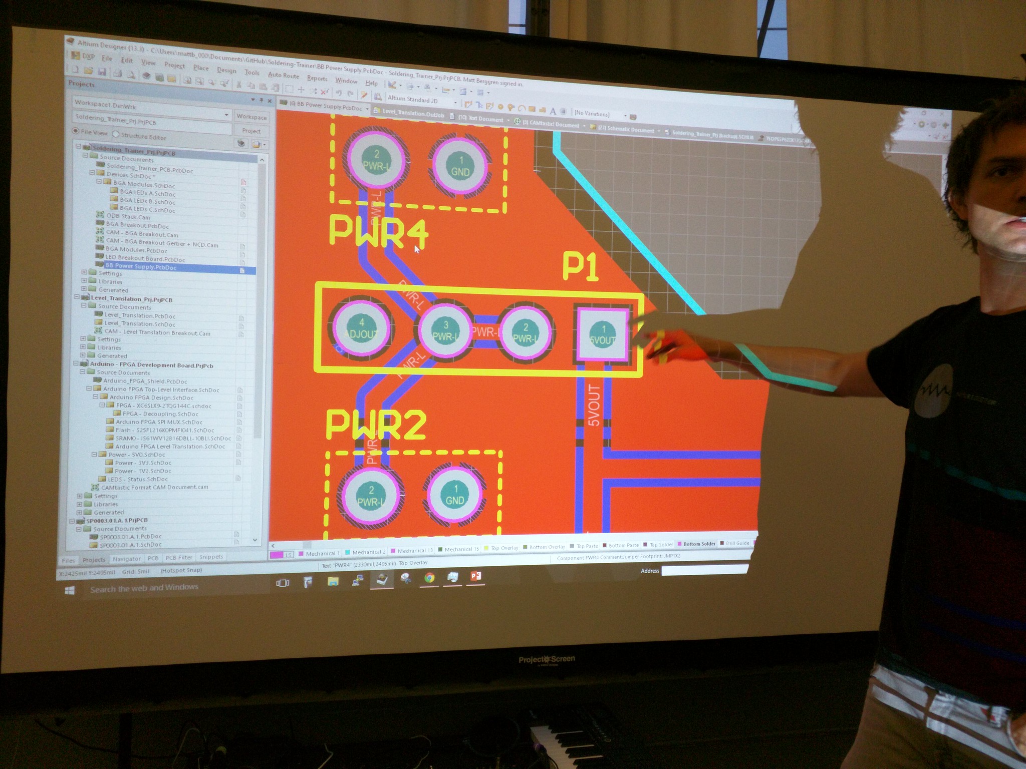
Here is the magic. On P1, which connects to left rail on the breadboard, by putting jumper on left 2 slots, we direct to 5V. By putting jumper on right 2 slots, we direct to adjustable power.
This is important, since when you are using Arduino, power is 5V, but other things you might want to use might be 3.3V. So this board allows us to use 5V on one side and other voltage on the other side :)
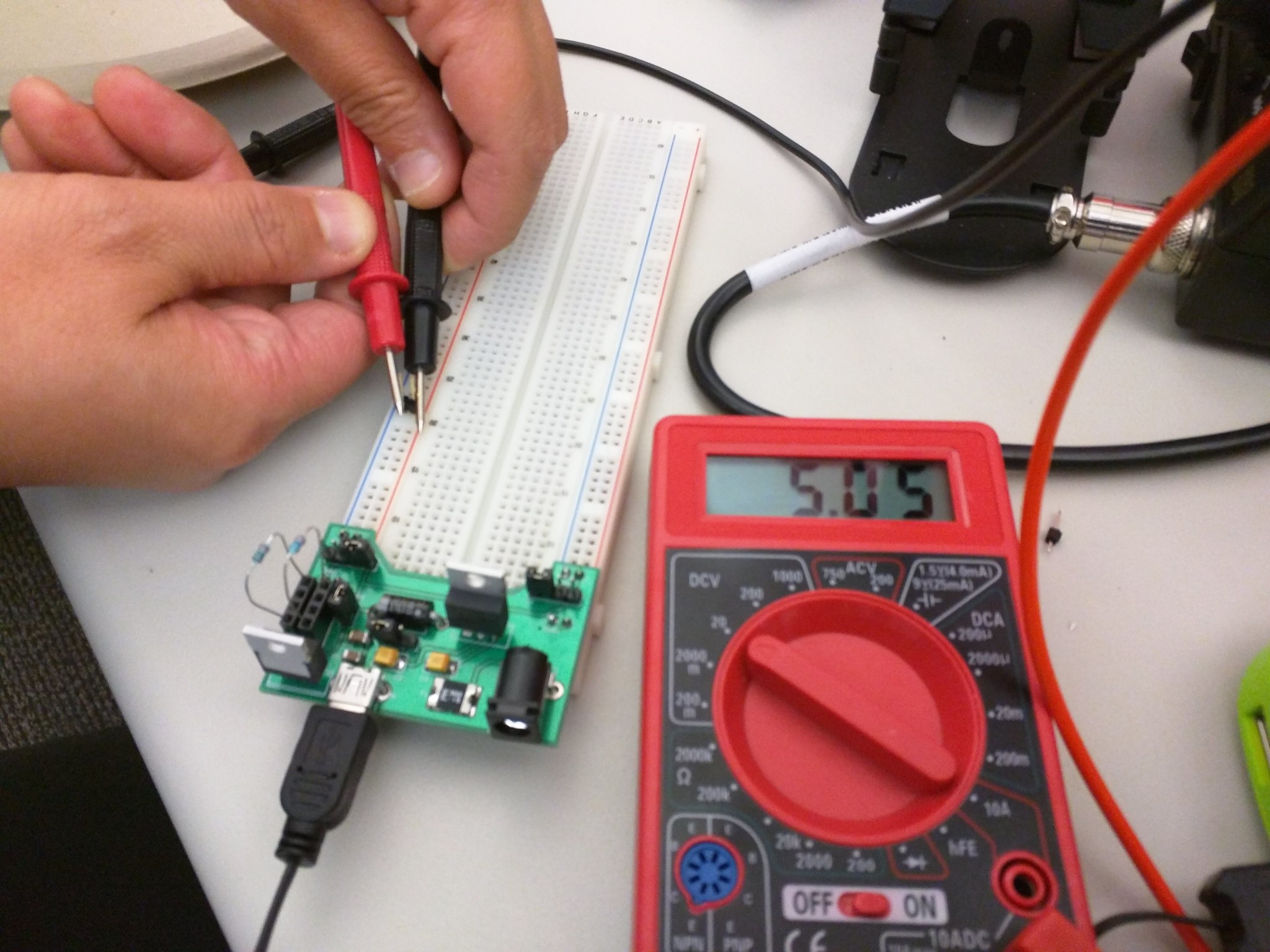
Testing that 5V mode works.
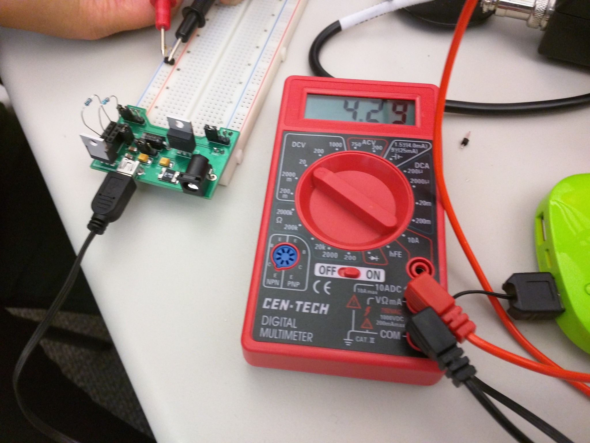
Testing that the adjustable mode works.
Similarly on P2, which connects to right rail on the breadboard, by putting jumper on left 2 slots, we direct to 5V. By putting jumper on right 2 slots, we direct to adjustable power.
The middle 3 slots directs where the power comes from. Left 2 will indicate power source is from USB, if we change the jumper to the right one, it directs to DC power source.
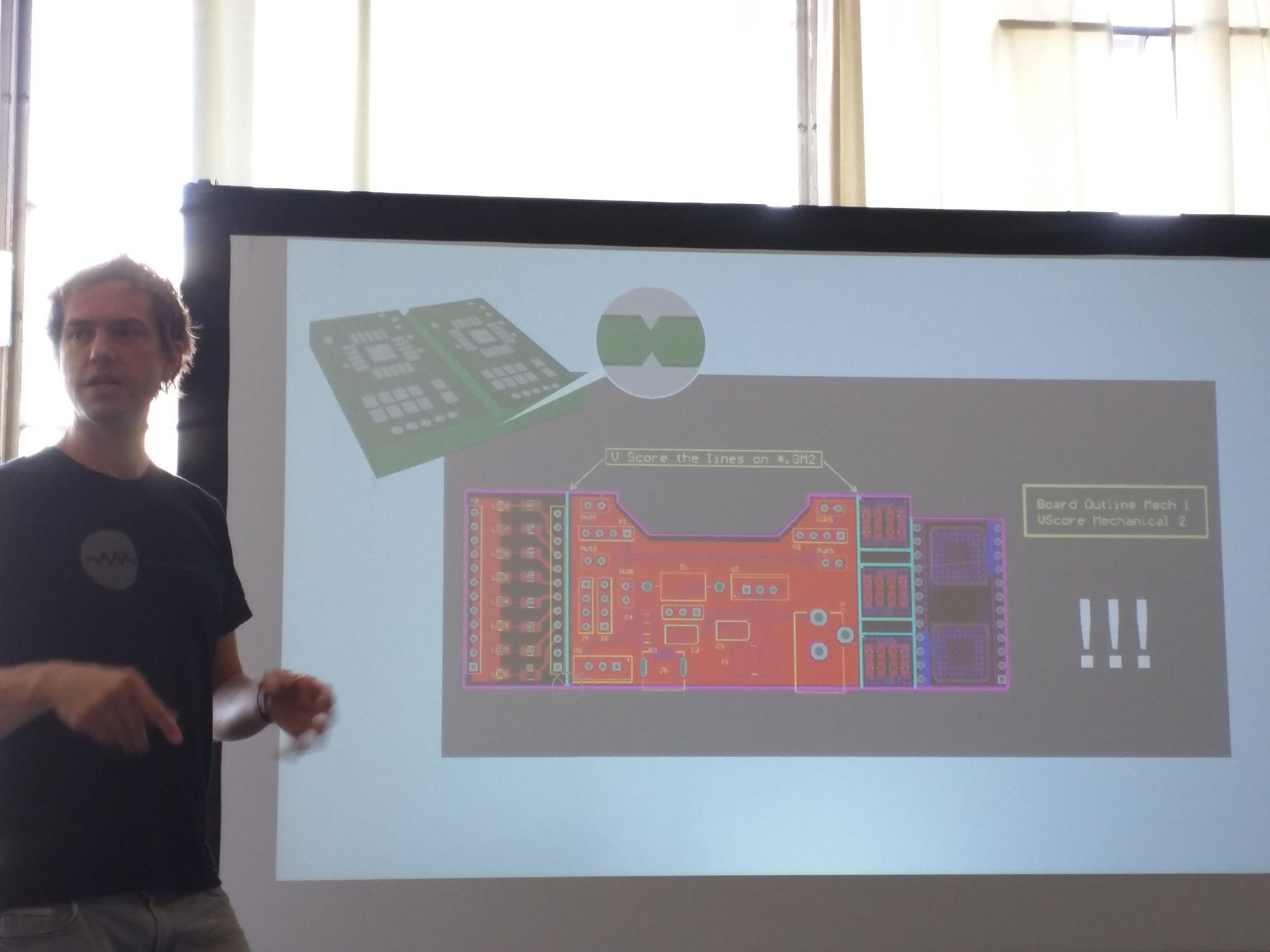
Board #3 – BGA-PCB test Platform
Here comes the hard part- we're doing BGA (ball grid array)!

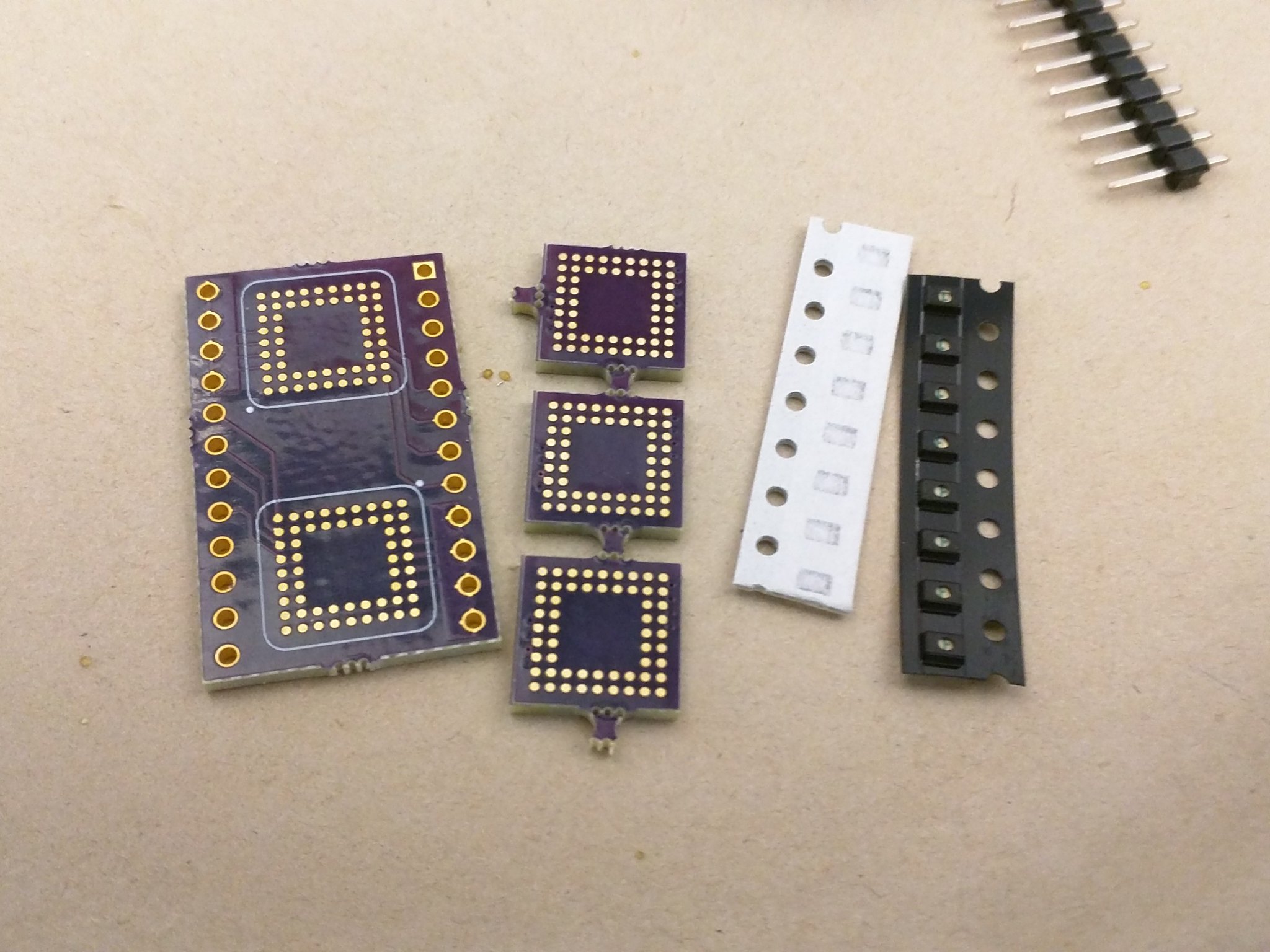
This is the parts we used.
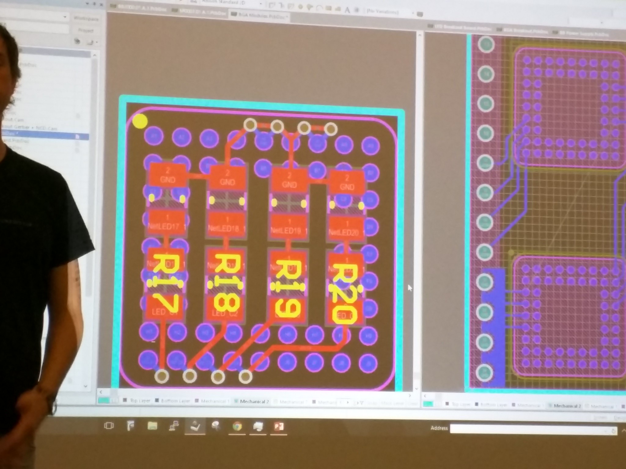
Schematics of resistors and LEDs.
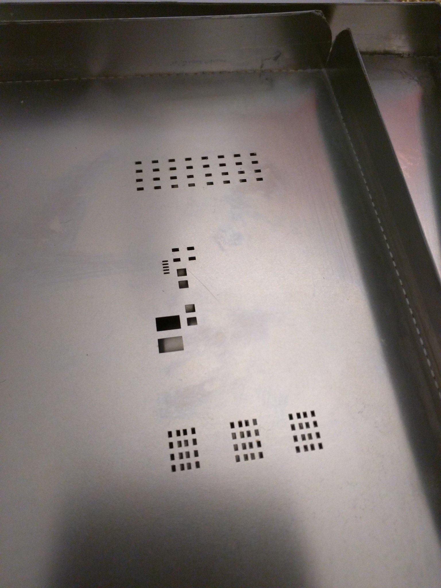
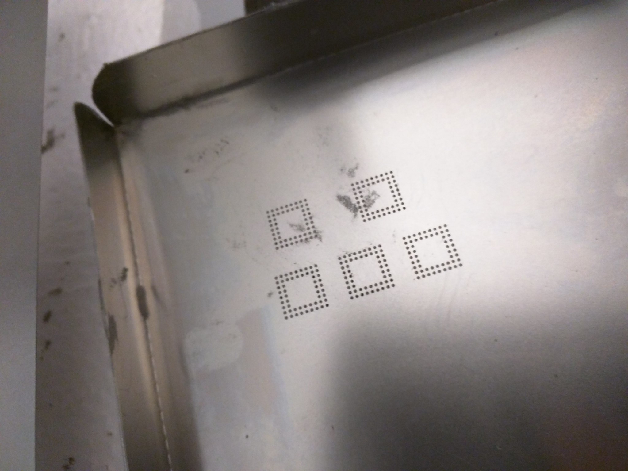
These are the stencils we used.
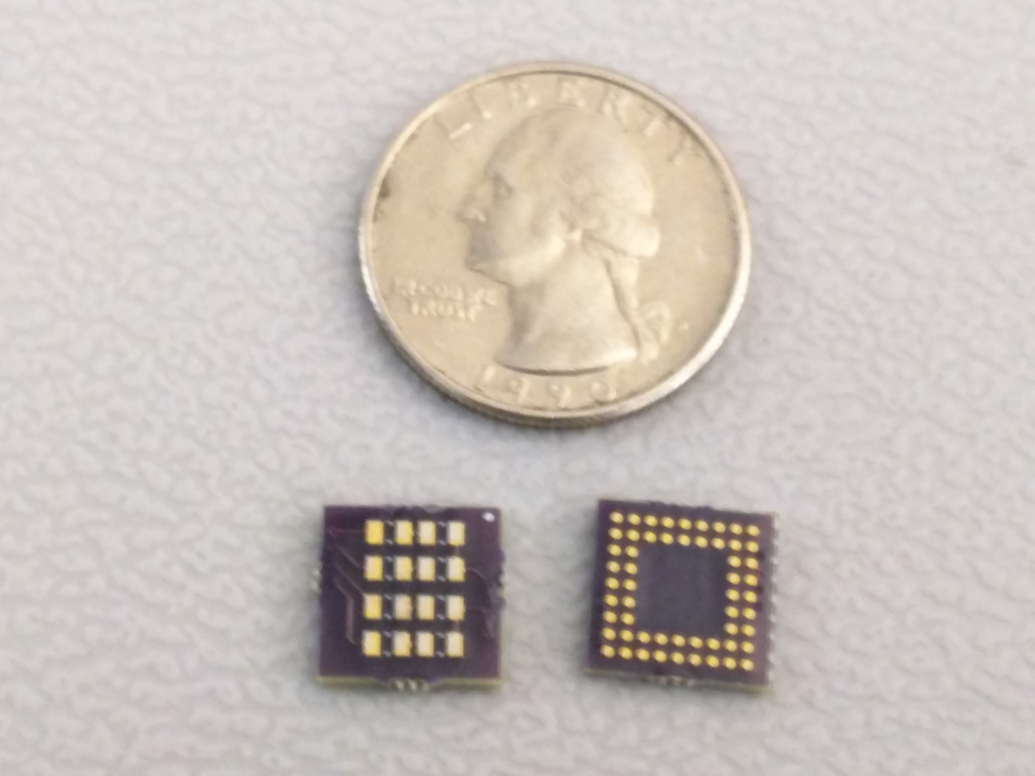
This is the boards- you can see it's tiny. Imagine how hard soldering on the back side of the board (right) is...!
Place the board under the stencil, put the solder paste on the stencil.
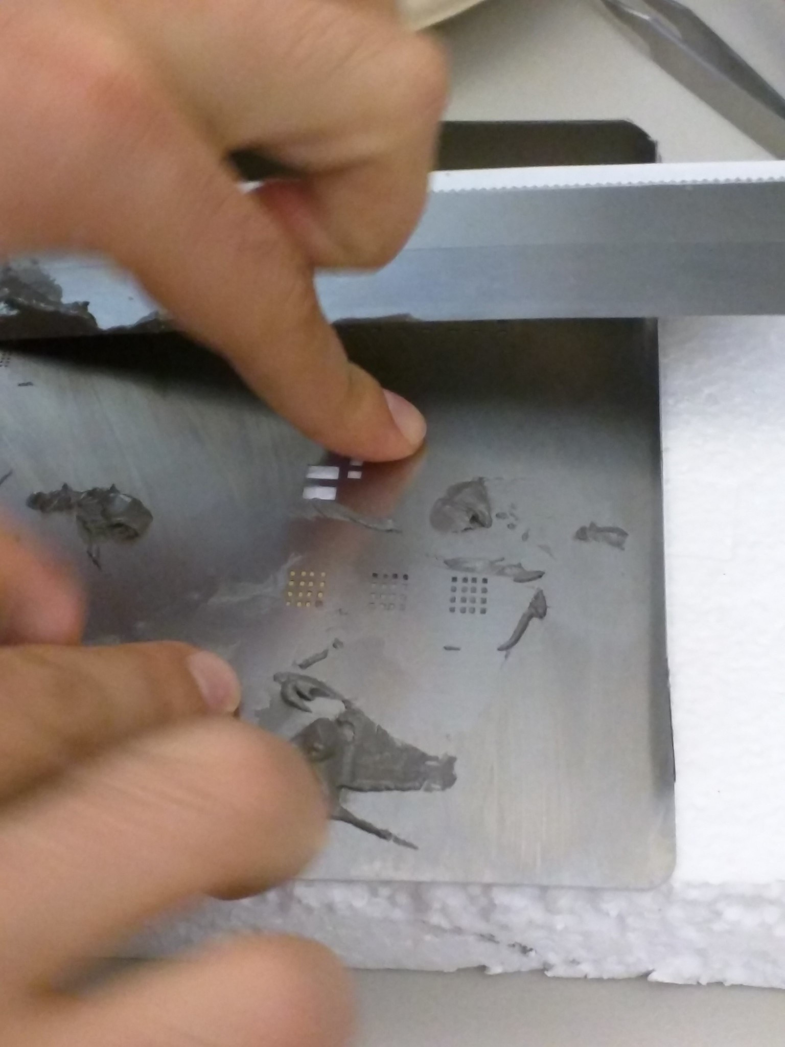
Place the resistors and LEDs on the solder paste. Heat it till the solder turns silver and shiny.
Turn it over and place the board under the stencil again, put the solder paste on the stencil- this is really really hard. I had to do it over many many many many times.
When you finally get the solder paste properly on the board, heat the board again, but be careful- if you overheat, the parts on the other side of the board will move.
I couldn't take any pictures of this process since my hands were dirty with the solder paste.
After both sides are done, put solder paste on the bigger board as well, and place the smaller board on top of the bigger one.

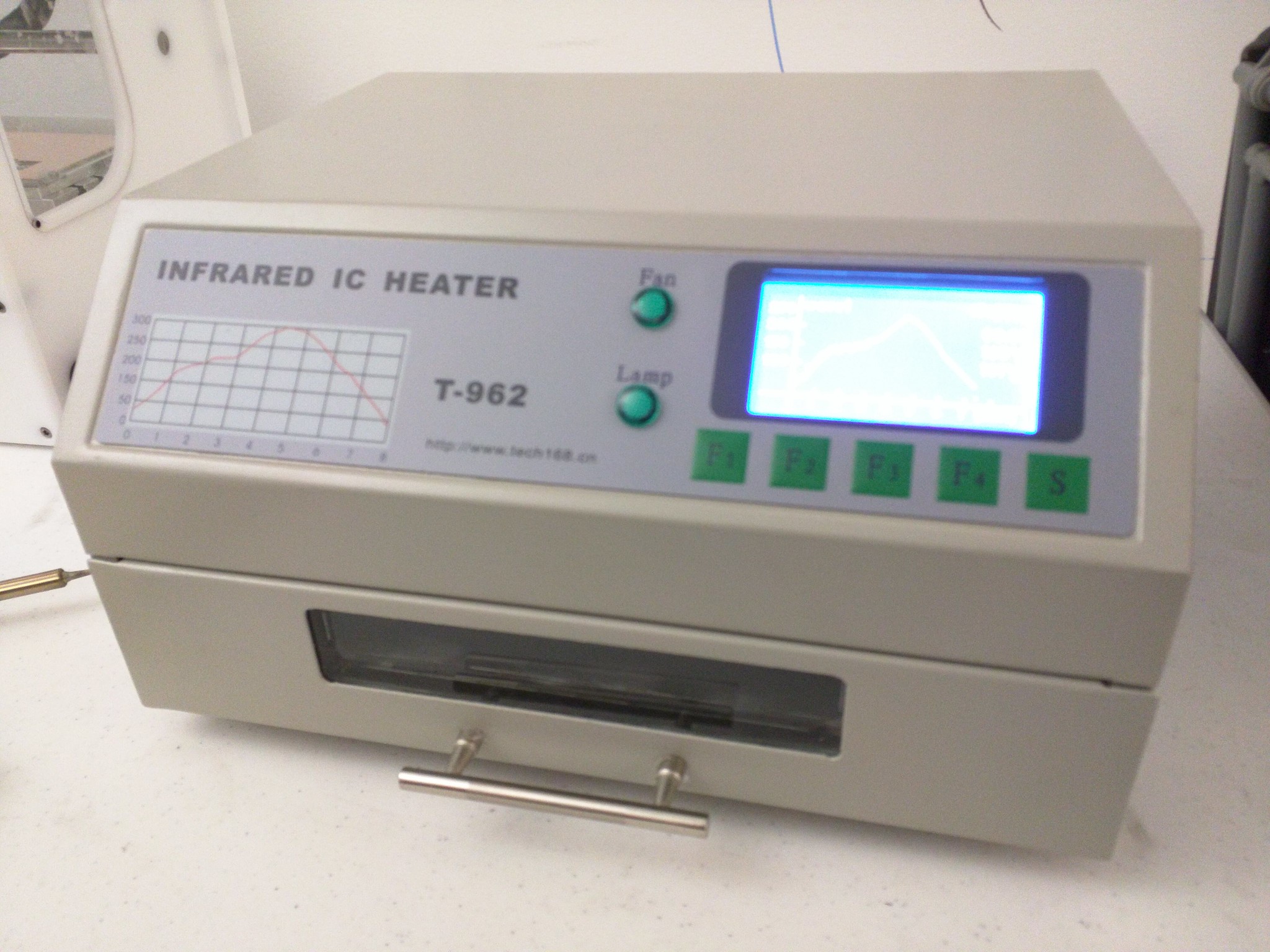
Put the board in the IC heater.
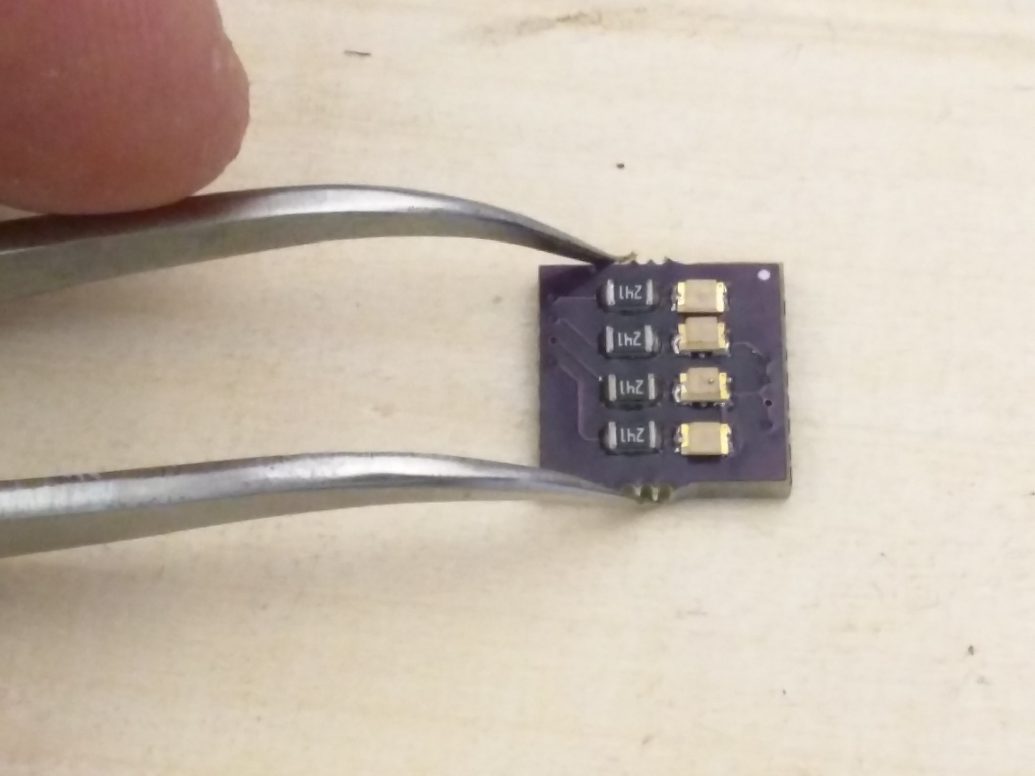
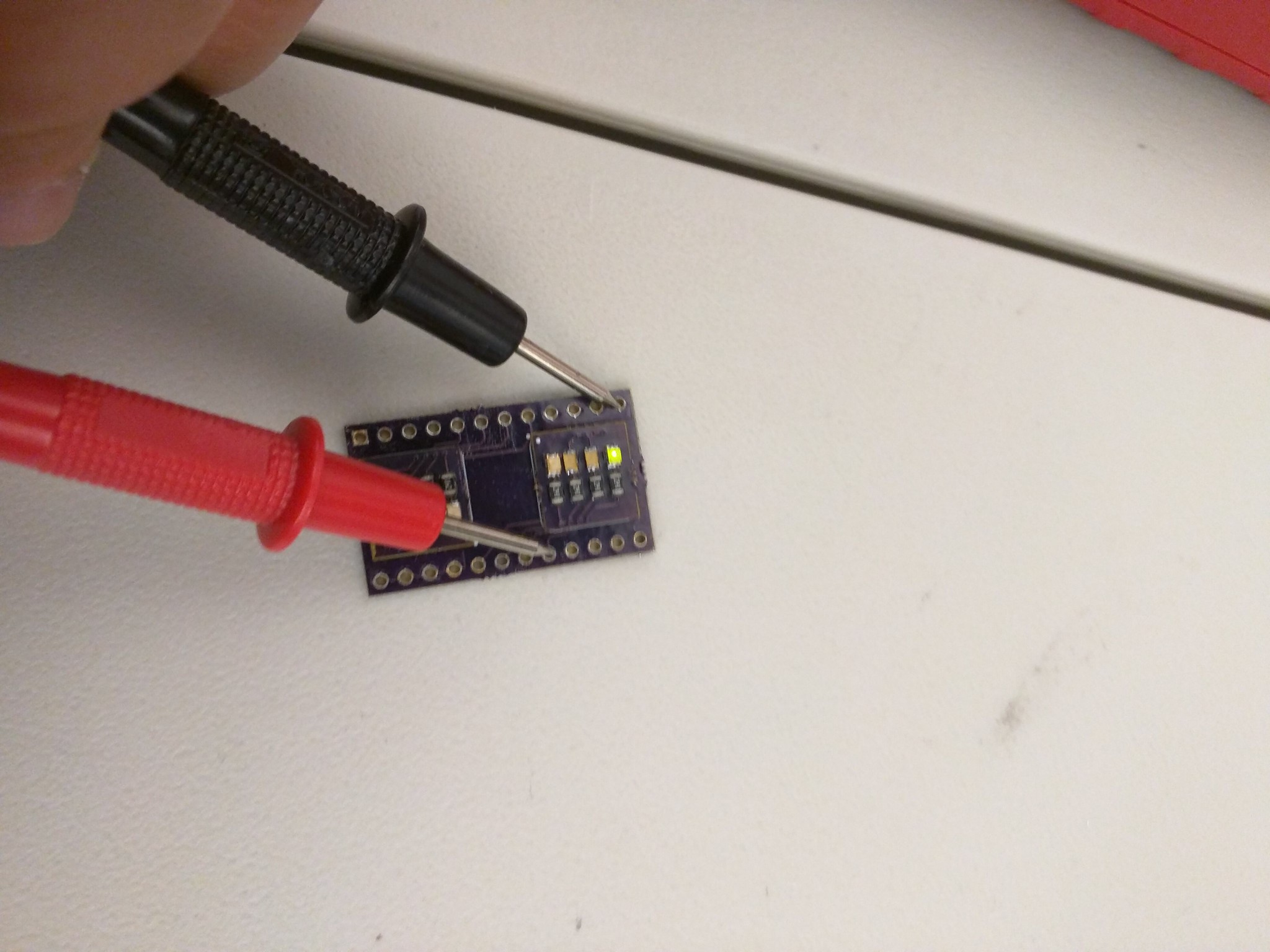
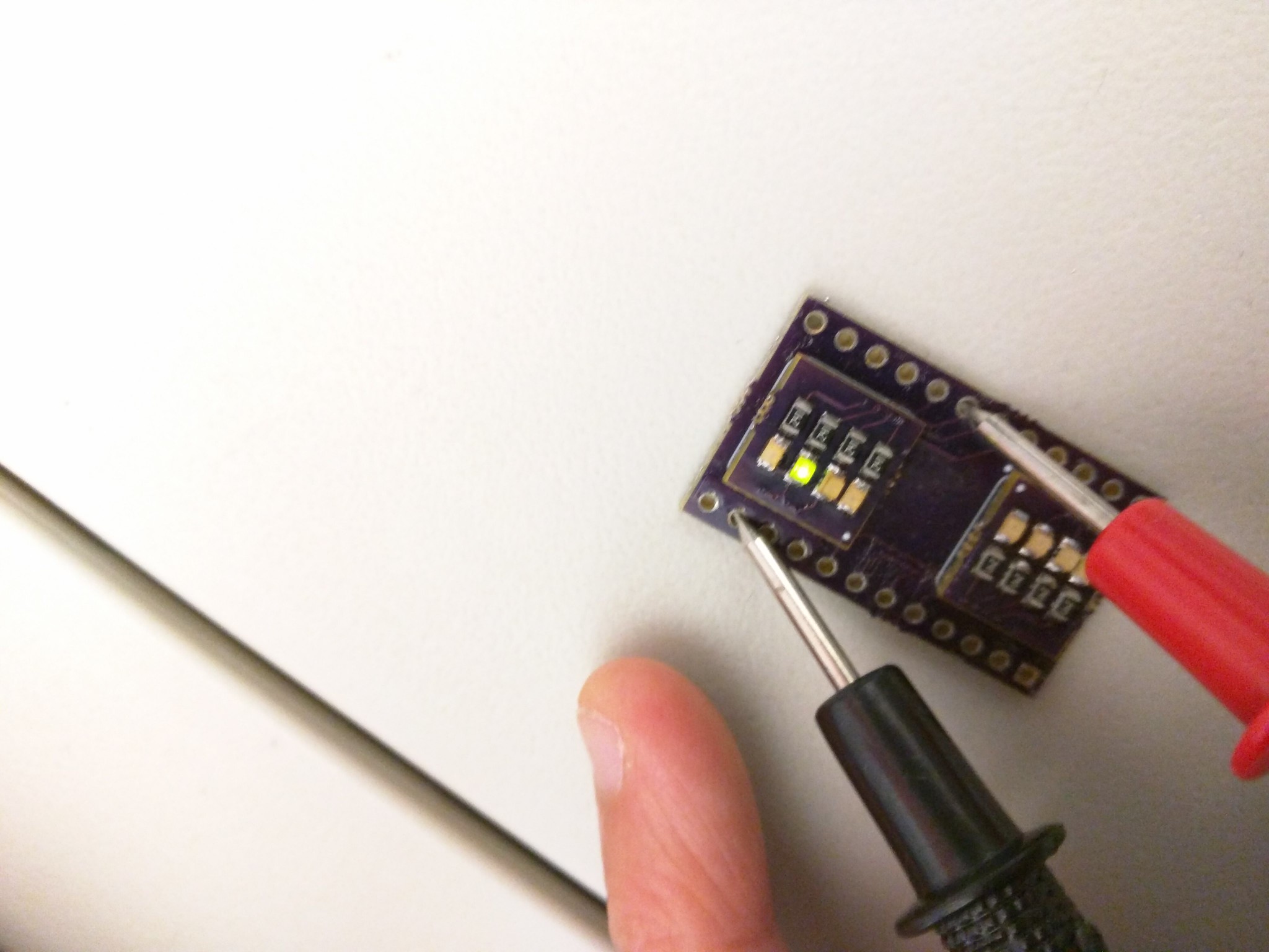
Done! And all LED works as intended...
And we're done!!


Thanks again Matt, and for those of you interested, his slides etc can be found here:
https://hackaday.io/matt
Disclaimer: The opinions expressed here are my own, and do not reflect those of my employer. -Fumi Yamazaki
It was organized by Matt Berggren. Thank you so much Matt!
We made 3 boards today:
Board #1 – Simple LED Breakout Board

This is the first board of the day... very simple :)
Soldered all of the resistors and LEDs.
Works!
Board #2 – Configurable Breadboard Power Supply


First step: solder the USB port. It's so tiny and hard!
Solder all other parts.
Here is the magic. On P1, which connects to left rail on the breadboard, by putting jumper on left 2 slots, we direct to 5V. By putting jumper on right 2 slots, we direct to adjustable power.
This is important, since when you are using Arduino, power is 5V, but other things you might want to use might be 3.3V. So this board allows us to use 5V on one side and other voltage on the other side :)
Testing that 5V mode works.
Testing that the adjustable mode works.
Similarly on P2, which connects to right rail on the breadboard, by putting jumper on left 2 slots, we direct to 5V. By putting jumper on right 2 slots, we direct to adjustable power.
The middle 3 slots directs where the power comes from. Left 2 will indicate power source is from USB, if we change the jumper to the right one, it directs to DC power source.
Board #3 – BGA-PCB test Platform
Here comes the hard part- we're doing BGA (ball grid array)!

This is the parts we used.
Schematics of resistors and LEDs.
These are the stencils we used.
This is the boards- you can see it's tiny. Imagine how hard soldering on the back side of the board (right) is...!
Place the board under the stencil, put the solder paste on the stencil.
Place the resistors and LEDs on the solder paste. Heat it till the solder turns silver and shiny.
Turn it over and place the board under the stencil again, put the solder paste on the stencil- this is really really hard. I had to do it over many many many many times.
When you finally get the solder paste properly on the board, heat the board again, but be careful- if you overheat, the parts on the other side of the board will move.
I couldn't take any pictures of this process since my hands were dirty with the solder paste.
After both sides are done, put solder paste on the bigger board as well, and place the smaller board on top of the bigger one.
Put the board in the IC heater.
Done! And all LED works as intended...
And we're done!!
Recommended tools by Matthew:


https://hackaday.io/matt
Disclaimer: The opinions expressed here are my own, and do not reflect those of my employer. -Fumi Yamazaki
0 件のコメント:
コメントを投稿